Introduction to Optical Distribution Network (ODN) in Optical Access Network:
What is ODN?
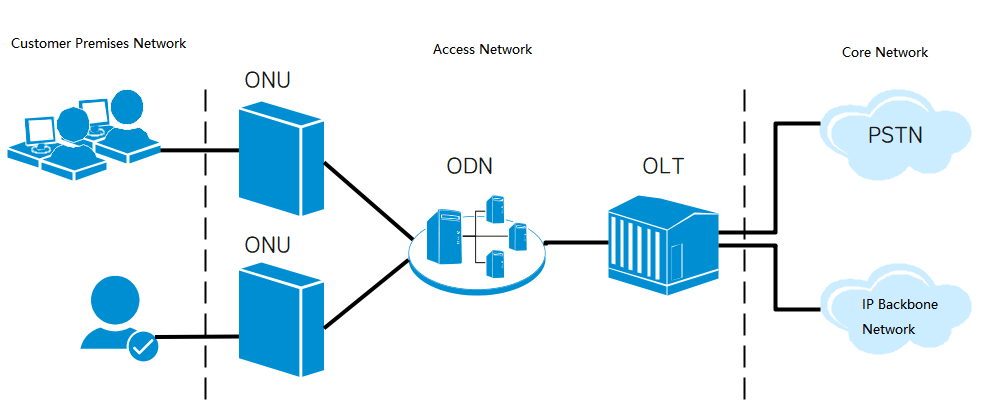
ODN stands for Optical Distribution Network, which is the optical transmission physical channel between the Optical Line Terminal (OLT) and the Optical Network Unit (ONU). Its primary function is to achieve bidirectional transmission of optical signals. Typically, it consists of optical fiber cables, optical connectors, optical splitters, and supporting equipment for installing and connecting these devices, with the most crucial component being the splitter. The optical distribution network (ODN) has two main splitting methods: one-level splitting and two-level splitting.
One-Level Splitting and Two-Level Splitting:
One-Level Splitting: The structure is OLT-Splitter-ONU, and the splitters between OLT and ONU are parallel. When using one-level splitting, the splitters are generally set at the distribution optical cross-connect point.
Two-Level Splitting: The structure is OLT-Splitter1-Splitter2-ONU, and the splitters between OLT and ONU are cascaded. When using two-level splitting, the first-level splitter is typically set at the distribution optical cross-connect point, and the second-level splitter is generally set at the fiber distribution hub.
One-level splitting can only connect one splitter, usually choosing splitters with a higher number of splits, such as 1:32 or 1:64. Two-level splitting typically uses 1:8 or 1:16 splitters at the first-level splitting point and 1:4 or 1:8 splitters at the second-level splitting point. Generally, a one-level splitting solution is used in congested urban or town areas to reduce costs and facilitate the maintenance of the Optical Distribution Network (ODN) nodes. On the other hand, a two-level splitting solution is used in roadside or rural locations to cover a broad range of ODN nodes, saving resources and funds.
**Working Principle of Optical Splitter:**
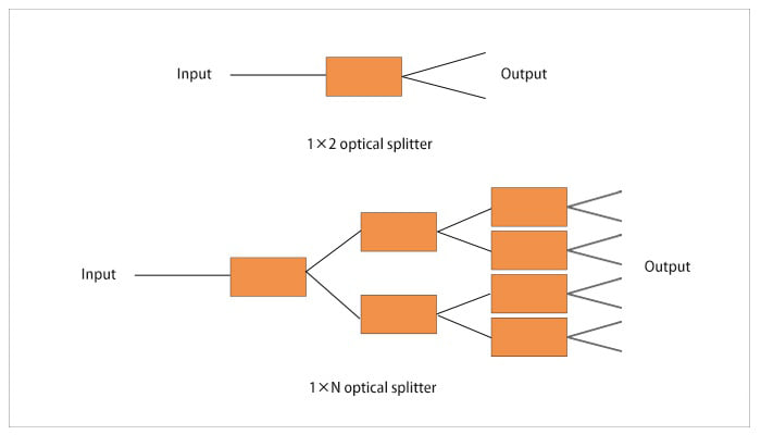
An optical splitter is a core passive component in FTTH systems. Also known as an optical coupler, it is an integrated waveguide optical power distribution device that divides an input optical signal into two or more output optical signals, evenly distributing the optical input power among all output ports. For instance, an optical splitter with a splitting ratio of 1:4 can evenly divide an optical signal into four parts, transmitting them in four different channels. Currently, the splitting ratios of optical splitters are typically 1:N or 2:N, such as 1:4, 1:8, 1:16, 1:32, 2:16, and 2:32.
The working principle of an optical splitter is as follows: When a single-mode optical fiber carries an optical signal, the optical energy is not entirely concentrated in the core for propagation; a small amount travels through the adjacent cladding. In other words, when the cores of two optical fibers are close enough, the mode field of the light transmitted in one fiber can enter the other fiber. The optical signal is then redistributed between the two optical fibers.
Optical Splitter vs. Wavelength Division Multiplexer (WDM):
In simple terms, a Wavelength Division Multiplexer (WDM) is a communication technology that combines a series of optical signals with different wavelengths into one bundle, transmitting along a single optical fiber. At the receiving end, these different wavelength optical signals are separated using a certain method. This technology enables the simultaneous transmission of multiple signals on a single optical fiber, with each signal being transmitted by light of a specific wavelength, known as a wavelength channel. Simultaneously allowing two or more optical wavelength signals to transmit information through different optical channels in the same fiber is referred to as Wavelength Division Multiplexing (WDM).
On the other hand, a splitter divides light of a single wavelength into multiple beams for propagation.
Classification of Optical Splitters:
Based on different splitting principles and manufacturing processes, optical splitters can be classified into two types: Fused Biconical Taper (FBT) and Planar Lightwave Circuit (PLC).
PLC Optical Splitter:
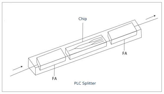
A PLC optical splitter (Planar Lightwave Circuit Splitter) is an integrated waveguide optical power distribution device based on a quartz substrate. Its main function is to distribute optical signals from one optical fiber to multiple optical fibers. The device consists of a splitter chip and fiber arrays at both ends, with the chip being the core component. The quality of the chip and the splitting channels directly affect the overall price of the splitter. The chip has one input and N output waveguides. The fiber arrays are located on the chip’s upper surface, enclosed in a housing, forming an optical splitter with one input and N output fibers.
Fused Biconical Taper (FBT) Optical Splitter:
The fused biconical taper (FBT) technique involves bundling two or more optical fibers with the coating removed, then melting and stretching them on a tapering machine. The splitting ratio is continuously monitored in real-time during the melting and stretching process. Once the desired splitting ratio is achieved, the process is stopped, and one end retains a single optical fiber (the rest is cut off) as the input, while the other end serves as the multi-output end.
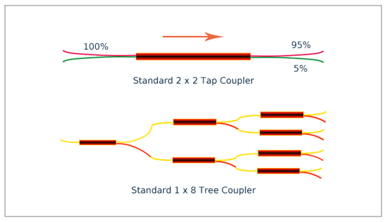
FBT vs. PLC:
One of the main differences between Fused Biconical Taper (FBT) and Planar Lightwave Circuit (PLC) splitters is their splitting ratio distribution.
The variable splitting of the tapered splitter is a significant advantage of this device. The FBT splitter allows for flexibility in achieving different splitting ratios. In contrast, the splitting in PLC splitters is uniform, distributing the signal evenly to users. For example, a 1×32 PLC splitter can evenly divide the optical signal into 32 parts, transmitting them in 32 different channels. In situations where there is inconsistency in the number of users and distances, and different optical power distributions are needed for various lines, FBT splitters with different splitting ratios may be used.
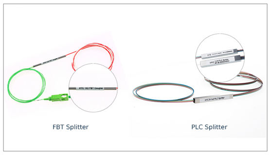
Classification of PLC Optical Splitters:
Additionally, optical splitters can be terminated with different types of connectors and are typically packaged in two ways: box-type or stainless steel tube-type. Box-type optical splitters generally use optical cables with outer diameters of 2mm or 3mm, while stainless steel tube-type optical splitters typically use optical cables with a 0.9mm outer diameter.
Device Structure:
Bare Fiber Type PLC Optical Splitter:
The bare fiber type PLC optical splitter leaves bare fiber at all of its ends. It is mainly suitable for applications where disassembly is infrequent, such as cable connector boxes and optical fiber distribution panels.
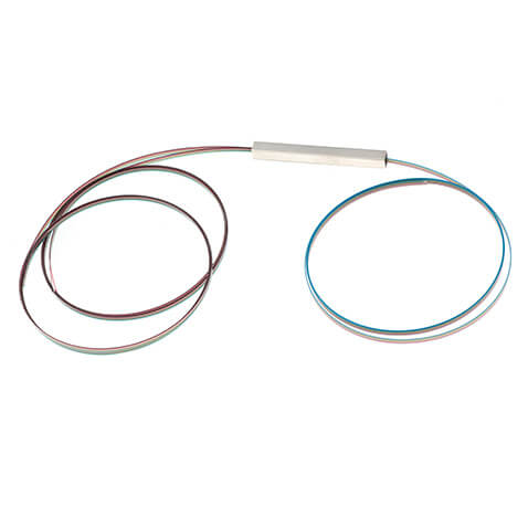
Micro Packaging Structure:
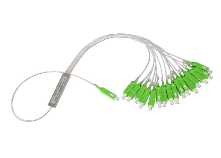
A micro optical splitter features a compact steel tube packaging and can be classified into types with and without connectorized lead fibers. Connectors typically include SC, LC, FC, and ST types. These splitters can be installed in optical cable joint boxes, module boxes, and distribution boxes.
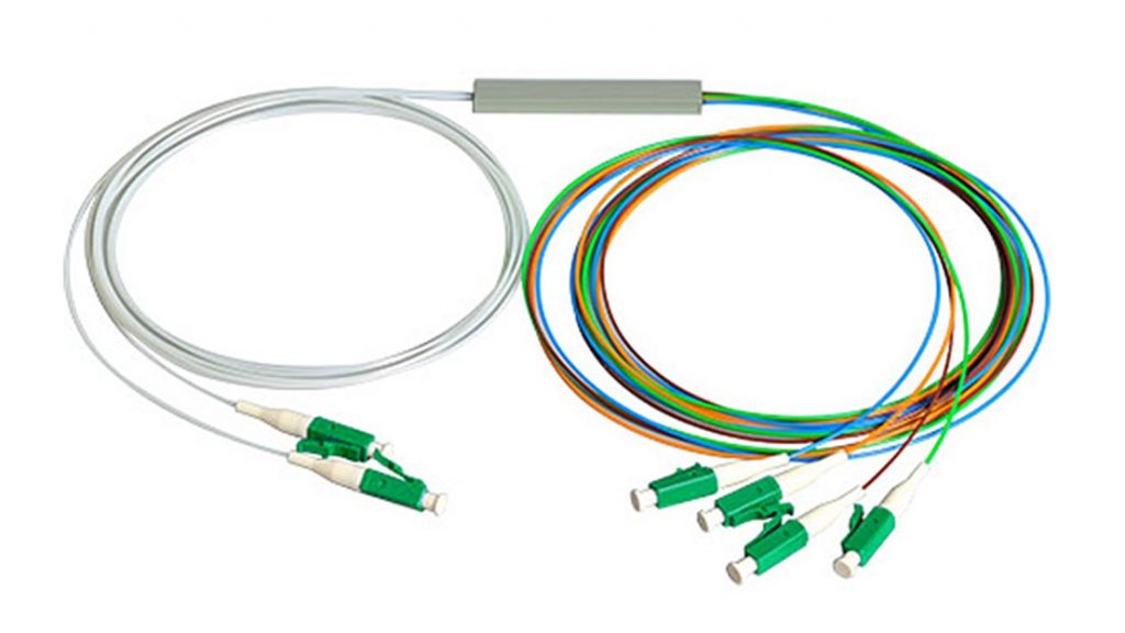
Fan-out Type PLC Splitter:
A fan-out type PLC splitter typically uses 0.9mm optical fibers and, through a fan-out kit, branches out individual optical fibers that can be terminated with different types of connectors. It can be effectively installed in fiber distribution point (DP) boxes, fiber junction boxes, or other small terminal boxes.
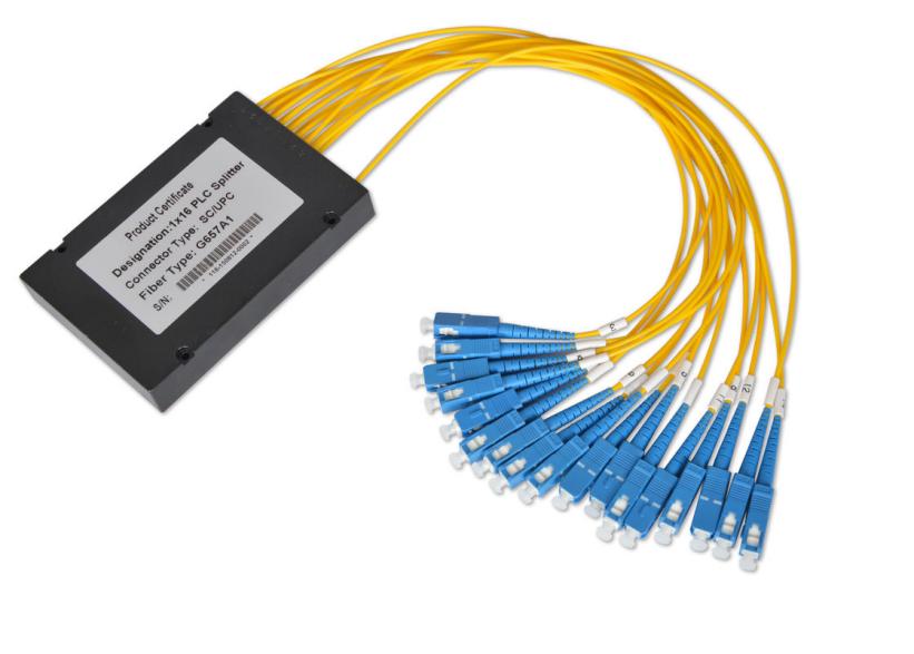
ABS Box-Type PLC Splitter:
Box-type packaged splitters are currently the most widely used type by various operators. The ABS packaging method is compact, offering greater flexibility in applications.
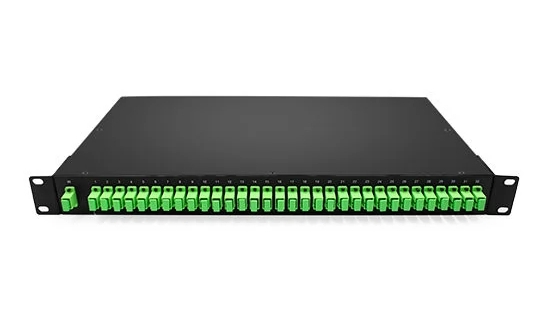
Rack-Mount PLC Splitter:
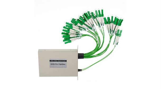
The rack-mount optical splitter is designed for installation in standard 19″ racks, meeting the high-density cabling requirements of data centers or server rooms. It typically uses metal box packaging, providing convenient installation in fiber optic projects and offering effective protection for PLC splitter devices. It comes with various adapter interfaces such as SC, LC, FC, or ST connectors. Rack-mount optical splitters are widely used in FTTX projects, cable TV systems, and data communication centers.
Wall-Mount PLC Splitter:
The housing of a wall-mount PLC splitter typically uses ABS material, providing reliable protection for direct, terminated, or branched connections of optical fibers. With a dual-layer structure, the upper layer houses the PLC splitter, while the lower layer contains a fiber fusion tray. Wall-mount optical splitters are used in the terminal access segment of FTTH access systems, facilitating the connection and protection of optical devices. They are suitable for hallways, basements, machine rooms, and are also applicable for outdoor wall-mounted and pole-mounted installations.
LGX-Type PLC Splitter:
In the LGX-type PLC splitter, the optical splitter is encapsulated in a small metal box that can be installed in a 19-inch 1U/2U/3U rack. With a pigtail-type structure for both input and output ends, it can be easily connected to adapter panels on ODF, saving time. The compact and plug-and-play design of LGX allows for convenient installation in fiber distribution boxes, ODF subframes, optical terminal boxes, and fiber cable distribution boxes.
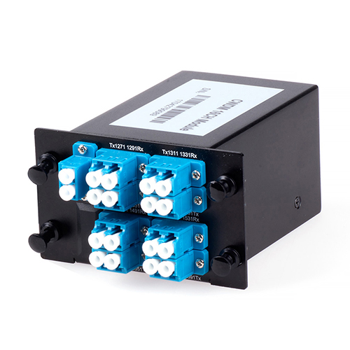
Module-Type PLC Splitter:
The module-type PLC splitter is fixedly installed in a module box, and interface types include SC/FC/LC, etc. It is mainly suitable for hallway or outdoor splitter points in the FTTH access mode. Commonly used 1×4, 8, 16, 32, and 2×8, 16, 32 PLC splitters serve as modules for installation in customer-specific boxes, especially in hallway boxes.
